Language:


When the door is fully open, the flow is too small. Can now
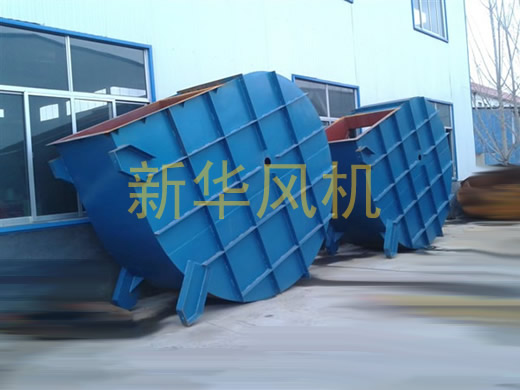
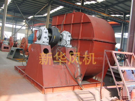
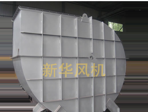
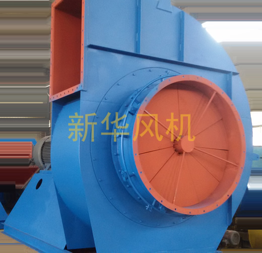
6-51-22#Centrifugal fan
|
Machine No. |
speed /(r/min) |
Total pressure /Pa |
flow /(m3/h) |
Internal efficiency (%) |
Internal efficiency /KW |
Shaft power /KW |
what is needed /KW |
Motor |
coupling |
Rolling bearing model |
|||
|
Model |
power /KW |
Model or
|
Fan shaft
/mm |
Motor
/mm |
|||||||||
|
8D |
1450 |
2525 |
9900 |
73 |
9.5 |
9.7 |
12 |
Y160L-4 380V |
4 |
5-65×42 |
65×140 |
42×110 |
3616 |
|
2524 |
12100 |
79 |
10.7 |
11 |
13 |
||||||||
|
2435 |
14300 |
82 |
11.8 |
12 |
14 |
||||||||
|
2346 |
16500 |
84 |
12.8 |
13.1 |
15 |
Y180M-4 |
18.5 |
5-65×48 |
48×110 |
||||
|
2169 |
18700 |
82 |
13.7 |
14 |
16 |
||||||||
|
1992 |
20900 |
79 |
14.6 |
14.9 |
17 |
||||||||
|
1771 |
23100 |
74 |
15.4 |
15.7 |
18 |
||||||||
|
9D |
1450 |
3195 |
14100 |
73 |
17.1 |
17.5 |
20 |
Y200L-4 380V |
30 |
5-65×55 |
65×140 |
55×110 |
3616 |
|
3194 |
17200 |
79 |
19.3 |
19.7 |
23 |
||||||||
|
3081 |
21200 |
82 |
21.2 |
21.6 |
25 |
||||||||
|
2969 |
23500 |
84 |
23.1 |
23.5 |
27 |
Y225S-4 380V |
37 |
5-65×60 |
60×140 |
||||
|
2745 |
26600 |
82 |
24.7 |
25.2 |
29 |
||||||||
|
2522 |
29700 |
79 |
26.3 |
26.9 |
31 |
||||||||
|
2241 |
33000 |
74 |
27.8 |
28.3 |
33 |
||||||||
|
10D |
1450 |
3944 |
19300 |
73 |
29 |
29.6 |
34 |
Y225M-4 380V |
45 |
5-65×60 |
65×140 |
60×140 |
3616 |
|
3943 |
23600 |
79 |
32.7 |
33.4 |
39 |
||||||||
|
3804 |
27900 |
82 |
36 |
36.7 |
43 |
||||||||
|
3666 |
32200 |
84 |
39 |
40 |
46 |
Y250M-4 380V |
55 |
5-65×65 |
65×140 |
||||
|
3389 |
36500 |
82 |
42 |
43 |
50 |
||||||||
|
3113 |
40800 |
79 |
45 |
46 |
53 |
||||||||
|
2767 |
45100 |
74 |
47 |
48 |
55 |
||||||||
|
11D |
1450 |
4772 |
25700 |
73 |
47 |
48 |
55 |
Y280S-4 380V |
75 |
6-65×75 |
75×140 |
75×140 |
3620 |
|
4771 |
31400 |
79 |
53 |
54 |
62 |
||||||||
|
4603 |
37100 |
82 |
58 |
59 |
68 |
||||||||
|
4436 |
42900 |
84 |
63 |
64 |
74 |
Y280M-4 380V |
90 |
||||||
|
4101 |
48600 |
82 |
68 |
69 |
80 |
||||||||
|
3767 |
54300 |
79 |
72 |
73 |
85 |
||||||||
|
3348 |
60000 |
74 |
76 |
77 |
89 |
||||||||
Contact: Mr Wu
Phone: 400-670-7798
Tel: 0533-6060097
Email: zbxinhuafan@163.com sales@xhblower.com
Add: The southern suburbs of the town industrial park Zhoucun Zibo Shandong

 xhblower